


Views: 0 Author: Site Editor Publish Time: 2026-10-13 Origin: Site


Modern electronics demand smaller footprints and higher flexibility. Engineers constantly face the challenge of fitting complex circuitry into shrinking device housings. This struggle highlights the critical connection between Flexible Printed Circuits (FPCs) and rigid Printed Circuit Boards (PCBs). Reliable interconnects prevent device failure and ensure seamless signal transmission. When you join these two different substrates, mechanical stress and thermal mismatch become major hurdles. Mastering this integration dictates the durability and performance of your final product. In this guide, you will explore the primary techniques for connecting flexible circuits to rigid boards. We will break down industry-standard bonding methods and precise equipment requirements. You will learn the exact physical mechanics behind these micro-joints. You will also discover actionable best practices for achieving flawless solder connections every single time.
Electronic designs increasingly rely on hybrid structures. Manufacturers use rigid boards to mount heavy components like microprocessors and power regulators. They use flexible circuits to route signals through tight spaces and moving hinges. This combination creates a highly capable but challenging assembly environment.
The primary difficulty lies in the material differences. Rigid boards typically use FR4 fiberglass. Flexible circuits rely on polyimide (PI) films. These materials possess drastically different Coefficients of Thermal Expansion (CTE). When the device heats up, the materials expand at different rates. This expansion creates massive shear stress at the connection point.
Engineers must create an interconnect capable of absorbing this stress. The joint must remain electrically conductive and mechanically sound over thousands of thermal cycles. Furthermore, the connection method must fit within strict volumetric constraints. Bulky connectors defeat the purpose of miniaturized designs. Therefore, selecting the optimal bonding technique requires a deep understanding of your specific application.
Table 1: Material Characteristics Impacting Integration
Property | Rigid PCB (FR4) | Flexible Circuit (Polyimide) | Integration Impact |
|---|---|---|---|
Flexibility | Rigid, inflexible | Highly dynamic | Creates a rigid-to-flex transition zone prone to cracking. |
Thermal Expansion | Low CTE (14-17 ppm/°C) | High CTE (up to 50 ppm/°C) | Generates shear stress on solder joints during heating. |
Moisture Absorption | Low | Relatively high | Requires pre-baking of FPC to prevent delamination during soldering. |
Thickness | Standard (1.6mm) | Ultra-thin (0.1mm) | Demands precise tooling to avoid crushing the flexible substrate. |
The electronics industry utilizes several methods to bridge flexible and rigid substrates. Your choice depends heavily on production volume, reliability requirements, and available board space. We categorize these methods into three primary families.
Zero Insertion Force (ZIF) and Board-to-Board (BTB) connectors represent the most traditional approach. You solder a surface-mount connector onto the rigid board. You then insert the flexible tail into this connector and lock it. This method allows for easy assembly and rework. You can replace a faulty screen or sensor without desoldering components.
However, mechanical connectors consume significant board real estate. They also add component costs to your bill of materials. In high-vibration environments like automotive applications, the mechanical latch can fail. Fretting corrosion can also degrade the contact pads over time, leading to intermittent signal drops.
ACF bonding uses a specialized adhesive film loaded with microscopic conductive particles. You place the film between the FPC and the rigid board. A heated thermode applies pressure to the joint. The pressure traps the conductive particles between corresponding pads, creating an electrical connection. The adhesive cures simultaneously to provide mechanical strength.
This method excels in ultra-fine pitch applications. It works perfectly for glass displays and delicate sensors. The low processing temperature protects sensitive components. However, ACF joints struggle with high-current power transmission. The adhesive can also degrade if exposed to extreme environmental moisture or heat.
Direct soldering creates a permanent metallurgical bond between the flexible circuit and the rigid board. This method offers the lowest electrical resistance and the highest mechanical strength. It eliminates the need for bulky mechanical connectors. Engineers rely on this technique for mission-critical medical devices and aerospace assemblies.
The most reliable way to achieve this direct bond is through pulsed heat technology, commonly known as hot bar soldering. This process requires specialized equipment and exact thermal management to prevent substrate damage.
Pulsed heat soldering stands as the gold standard for high-reliability permanent interconnects. The process relies on a resistive heating element pressing down on the flexible circuit. The flexible circuit features exposed copper pads. These pads align perfectly with pre-tinned pads on the rigid board.
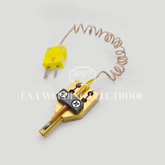
The heart of this process is the Hot Bar Heater Tip. This specialized tooling piece generates heat through electrical resistance. A closed-loop power supply sends a massive pulse of DC current through the metal tip. The tip heats up almost instantly. It transfers this thermal energy directly through the Kapton tape and polyimide substrate into the solder joint.
The process follows a strict thermal profile. First, the thermode descends and applies mechanical pressure to the parts. This ensures intimate contact and eliminates air gaps. Next, the power supply pulses the current. The temperature ramps up to the reflow point of the solder alloy. The heat dwells for a few seconds to allow the solder to melt and form an intermetallic compound (IMC) layer.
Crucially, the power supply then shuts off the current. The thermode remains in place, maintaining constant pressure while forced air cools the joint. The solder solidifies while under compression. This prevents any movement during the phase change. The result is a structurally perfect, void-free solder joint.
Achieving a flawless bond requires mastering thermal dynamics. Heat must flow uniformly across the entire array of contact pads. A temperature variance of even a few degrees can cause catastrophic defects. Cold spots result in weak joints. Hot spots scorch the flexible substrate and destroy trace adhesion.
You need a high-quality hot bar heater tip for FPC bonding to guarantee this uniformity. Engineers design these tips to distribute heat evenly along their entire length. They achieve this by varying the cross-sectional area of the metal. The machining process must be flawless. Any imperfection alters the electrical resistance, which in turn alters the temperature profile.
A built-in thermocouple monitors the temperature continuously. It sits welded precisely at the heating junction. The control system reads this feedback hundreds of times per second. It adjusts the electrical current instantaneously to match your programmed thermal profile. This closed-loop control guarantees repeatability across thousands of production cycles.
The success of your manufacturing line depends entirely on your tooling. You cannot compensate for poor tooling with software tweaks. The physical interface between the machine and your product dictates the yield rate.
Manufacturers typically craft the precision hot bar heater tip from specialized alloys. Molybdenum and titanium represent the most common choices. These materials offer high electrical resistance and excellent dimensional stability at elevated temperatures. More importantly, they resist solder wetting. Solder will not stick to the thermode face. This prevents the tool from lifting the flexible circuit when it retracts.
Standard flat designs work for simple assemblies. However, modern electronics often feature crowded board layouts. Tall components like capacitors or shielding cans often sit millimeters away from the bond area. In these cases, you require a specialized FPC to PCB soldering tip. Engineers machine these custom tips with complex 3D profiles. They include cutouts and reliefs to clear adjacent components while still delivering uniform pressure to the pads.
Developing these complex geometries requires deep metallurgical expertise. You must partner with a reliable custom heater tip supplier. An experienced supplier simulates the thermal dynamics before machining. They ensure that cutting a relief into the metal does not create an unintended cold spot over your critical traces.
Even the best equipment requires disciplined process control. You must optimize every variable in the assembly environment. Follow these best practices to maximize your production yield.
Control Solder Volume: Inconsistent solder paste deposition causes erratic results. Use precise stencils to apply the exact volume of solder to the rigid board pads. Pre-tinning the pads ensures a consistent metallurgical baseline.
Apply Proper Flux: Flux removes oxidation and promotes solder wetting. Use a high-quality, no-clean flux. Apply it sparingly. Excessive flux boils during heating, creating gas voids inside the joint. It also leaves sticky residue that attracts dust.
Ensure Coplanarity: The thermode face and the product fixture must remain perfectly parallel. Use pressure-sensitive carbon paper during setup. Press the cold thermode onto the paper. Inspect the resulting footprint. A uniform dark line indicates perfect coplanarity. A faded edge requires immediate mechanical adjustment.
Design Thermal Reliefs: Copper traces act as heat sinks. If one pad connects to a massive ground plane while the adjacent pad connects to a thin signal trace, they will heat at different rates. Design thermal reliefs into your PCB layout to balance the thermal mass across all pads.
Maintain Cleanliness: Operator handling introduces skin oils to the contact pads. These oils prevent solder wetting. Always handle flexible circuits using cleanroom gloves. Inspect the pads under magnification before bonding.
Experience reveals several recurring errors in hybrid circuit assembly. Avoiding these pitfalls saves significant scrap costs and prevents field failures.
Many operators apply too much downward pressure. They assume higher pressure yields a stronger bond. In reality, excessive pressure crushes the polyimide film. It also squeezes the molten solder out from between the pads, causing shorts between adjacent traces. You only need enough pressure to maintain intimate contact and prevent movement.
Another common mistake involves improper cooling. Operators sometimes program the machine to lift the thermode immediately after the heat cycle ends. The solder remains in a liquid or plastic state. As the flexible circuit relaxes, it pulls away from the board. This creates microscopic fractures inside the joint. Always program a cooling dwell time. The thermode must hold pressure until the temperature drops below the solder alloy's solidus point.
Finally, engineers often neglect the fixture design. The base tooling must support the rigid board perfectly. If the board flexes downward under the pressure of the thermode, it destroys the coplanarity. Use precision-machined aluminum or ceramic fixtures to support the assembly from below.
When defects occur, you need a systematic approach to identify the root cause. Visual inspection under a microscope provides the first clues. X-ray inspection reveals internal voids. Cross-section analysis confirms the intermetallic compound thickness.
Chart 1: Troubleshooting Common Bonding Defects
Defect Type | Visual Appearance | Probable Root Cause | Corrective Action |
|---|---|---|---|
Cold Solder Joint | Dull, grainy, or irregular solder fillets. Solder did not wet properly. | Insufficient peak temperature or inadequate flux application. | Increase thermode dwell time. Verify thermocouple integrity. Clean pads. |
Solder Bridging | Solder connects two adjacent pads, creating a dead short. | Excessive solder volume or excessive downward mechanical pressure. | Reduce stencil thickness. Lower pneumatic cylinder pressure settings. |
Substrate Delamination | Blisters or bubbling on the flexible Kapton/Polyimide film. | Moisture trapped in FPC or temperature set too high. | Pre-bake flexible circuits to remove moisture. Lower peak profile temperature. |
Inconsistent Wetting | Left side of the array looks perfect, right side shows no bonding. | Severe coplanarity issue between the thermode tip and the base fixture. | Re-align the bonding head. Check fixture for debris. Perform carbon paper test. |
Routine maintenance ensures consistent quality. Establish a strict calibration schedule for your bonding equipment. Perform these checks daily before beginning production runs.
Clean the thermode surface using a designated ceramic brush. Remove all oxidized flux residues. Never use steel wool or abrasive files.
Inspect the thermocouple wire for fraying or damage. A loose thermocouple causes runaway heating.
Run a dry profile test without a product. Monitor the temperature curve on the software. Ensure the ramp rate and peak temperature match your specifications.
Verify the pneumatic cylinder pressure. Use a calibrated load cell to confirm that the programmed pressure matches the actual physical force applied to the parts.
Check the fixture alignment pins. Ensure they hold the rigid board and flexible circuit securely without excessive play.
Perform a destructive peel test on the first article of the shift. The flexible substrate should tear before the solder joint breaks.
Connecting flexible circuits to rigid boards remains a critical challenge in modern electronics manufacturing. Your choice of integration directly affects product lifespan, signal integrity, and overall form factor. While mechanical connectors offer convenience, direct pulsed heat soldering provides unmatched durability and electrical performance.
Success in this process relies heavily on precision engineering and strict process control. You must respect the thermal dynamics of different materials. By investing in high-quality, custom-machined tooling, you eliminate the variables that cause inconsistent joints. Implement robust coplanarity checks, manage your solder volumes, and strictly control your thermal profiles.
Take action by auditing your current assembly processes today. Verify your equipment calibration and inspect your heating elements for wear. Partnering with seasoned tooling experts ensures your production line maintains high yields. When you master these techniques, you guarantee that your complex hybrid electronics will survive the demands of the real world.
A: The ideal temperature depends entirely on your specific solder alloy. For common lead-free SAC305 solder, the peak tip temperature usually ranges between 280°C and 320°C. You must profile the process to ensure the actual solder joint reaches around 240°C without burning the polyimide substrate.
A: ACF serves as a fantastic alternative for ultra-fine pitch applications or highly temperature-sensitive components. However, it cannot replace soldering for high-current power connections. Soldering provides superior mechanical strength and significantly lower electrical resistance, making it mandatory for rugged environments.
A: Operators should inspect and clean the thermode at least once per production shift. They must use a soft ceramic brush or a designated non-abrasive cleaning pad to remove flux residue. Using aggressive metal tools scratches the face, which permanently destroys its thermal uniformity.
A: Burn marks usually stem from an overly aggressive thermal profile or uneven pressure distribution. If the heating cycle lasts too long or the peak temperature spikes too high, the polyimide degrades. Check your closed-loop feedback system and ensure your tooling exactly matches the pad layout.


