


Views: 0 Author: Site Editor Publish Time: 2026-09-27 Origin: Site


As electronics miniaturize, modern assembly lines face immense pressure. Engineers pack more power into smaller product footprints. This design trend pushes standard manufacturing processes beyond their physical limits. Achieving reliable, high-yield electromechanical connections between flexible printed circuits (FPCs) and rigid boards becomes increasingly difficult. Standard reflow ovens often damage sensitive components. Hand-soldering methods introduce unacceptable human error. Parts warp under uneven thermal stress. Connections fail prematurely in the field.
Hot bar soldering, also known as thermode soldering, directly solves these assembly issues. It is a highly controlled pulsed-heat process. The system supplies localized heat and mechanical pressure simultaneously. However, equipment alone does not guarantee perfect joints. The success of this process relies almost entirely on your tooling. Joint reliability, minimal thermal damage, and high throughput depend heavily on the precision of the Hot Bar Heater Tip.
We will thoroughly evaluate key hot bar soldering applications. You will learn to analyze mechanical variables impacting production yields. Furthermore, we define strict criteria for selecting precise tooling and capable suppliers for high-volume manufacturing lines.
Hot bar soldering solves specific coplanarity and thermal mass challenges where standard reflow ovens fail, particularly in flex-to-rigid (FPC-to-PCB) assemblies.
Process repeatability is highly dependent on the metallurgy, 3D geometry, and thermal profiling of the hot bar heater tip.
Upgrading to automated hot bar systems requires evaluating machine rigidity, closed-loop thermal feedback, and alignment tolerances.
Partnering with an experienced custom heater tip supplier mitigates production downtime caused by premature tip wear, uneven heat distribution, or poor coplanarity.
Understanding thermode technology requires looking at the physical phase changes occurring during the bonding cycle. The mechanics differ vastly from ambient heating methods. We break the pulsed-heat process down into three highly controlled sequential stages.
Pre-heat Stage: The thermode descends onto the parts. The system applies mechanical pressure. A controlled electrical pulse rapidly heats the tool. This initial temperature spike activates the flux. It removes surface oxides from the mating pads.
Reflow Stage: The system drives the temperature higher. It reaches the exact melting point of the specific solder alloy. The liquid solder wets the pad surfaces. The thermode maintains constant downward pressure. This prevents any component shifting.
Cool-down Stage: The electrical current stops. Airflow cools the thermode rapidly. Crucially, the system holds mechanical force. Pressure remains constant until the solder solidifies completely. The tool retracts only after forming a solid, secure joint.
We must frame this within the broader business problem of assembly yields. Contrast this highly targeted method against traditional reflow ovens. Reflow processing subjects the entire PCB assembly to aggressive heat profiles. This ambient soaking risks damaging thermally sensitive components. Plastics melt. Batteries degrade. Displays suffer pixel damage.
Hot bar technology isolates the thermal energy. It applies heat only where required. The localized approach protects adjacent sensitive parts. Furthermore, simultaneous mechanical pressure holds parts perfectly flat. It stops flexible circuits from lifting during the crucial solder phase change.
However, we must acknowledge the implementation reality. While thermode bonding reduces overall thermal stress, it introduces new engineering constraints. You must follow strict pad design rules. Traces require specific spacing. Operators must apply flux precisely. Too much flux creates voids. Too little flux causes poor wetting. Finally, you need exact coplanarity of the thermode tool. If the tip rests unevenly, it creates inconsistent solder joints across the pad array.
Always profile your temperature directly at the solder joint. Do not rely solely on the thermode display temperature. Thermal transfer loss always occurs between the heater and the component. You must account for this delta in your machine programming.
Thermode processing requires specialized equipment. You should reserve this method for connections where standard techniques fail. We see the highest return on investment in a few distinct manufacturing scenarios.
FPC-to-PCB Bonding: Flexible cables naturally resist laying flat. They curl and warp when heated. Reflow ovens cannot manage this physical lifting. You need downward pressure during cooling. This prevents the flex cable from peeling away before the solder freezes. Utilizing a precision FPC bonding heater tip ensures uniform pressure across every single trace.
Heat Seal Connectors (HSC) & ACF Bonding: Display manufacturing relies heavily on thermode technology. LCDs require fine-pitch connections. Anisotropic Conductive Film (ACF) relies on precise temperature and force to trap conductive particles. The hot bar crushes these microscopic spheres between the pads. This creates reliable vertical conductivity.
Wire-to-Board Connections: Assembly lines often struggle with high-frequency coaxial cables. Ribbon cables also present challenges. Operators usually strip insulation manually. They solder wires individually. Thermode systems combine these steps. The heated tool melts the insulation. It reflows the solder underneath in one repeatable cycle.
You must also apply a strict evaluation lens. Know when to avoid hot bar applications. Do not use this process for standard Surface Mount Devices (SMDs). Pick-and-place machines paired with standard reflow ovens remain vastly superior for passive components. They offer unmatched speed. They deliver better cost efficiency for simple rigid-board populations.
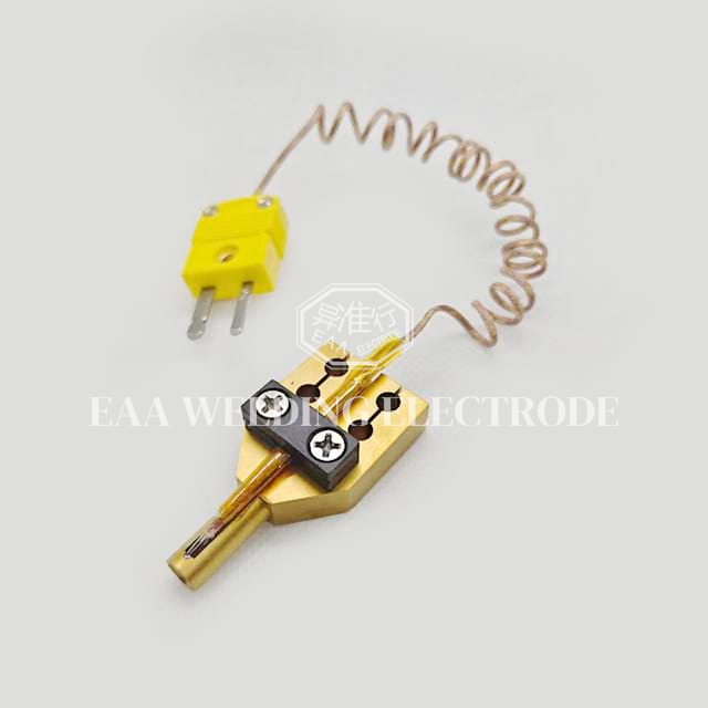
Process repeatability acts as the foundation of profitable manufacturing. In pulsed-heat systems, the tool itself drives this consistency. The 3D design of the heating element dictates the thermal gradient completely. Poorly engineered tips create disastrous results on the line.
Thermal transfer dynamics require perfect physical contact. If a tip features uneven geometry, it generates cold spots. Cold spots fail to melt the alloy. This leaves weak, brittle joints. Conversely, bad designs generate hot spots. Excessive localized heat burns the PCB substrate. It causes immediate delamination of the copper pads.
Material selection and metallurgy determine performance longevity. Manufacturers typically machine these tools from specialty metals. Molybdenum and titanium alloys dominate the industry. Molybdenum offers exceptional thermal conductivity. It heats and cools rapidly. Crucially, it resists solder wetting. Liquid solder does not stick to molybdenum readily. This keeps the tool clean. However, molybdenum proves incredibly difficult to machine. It requires advanced manufacturing techniques to achieve strict flatness tolerances.
Thermocouple integration represents another critical factor. Fast temperature feedback requires accurate sensor placement. Front-mounted thermocouples sit closer to the joint. They react quickly to temperature drops. Top-mounted versions sit further away. They often create lag in the closed-loop feedback system. Responsive pulse heating demands immediate data from the working face.
We must also address the severe risk factor of tip wear. Continuous pressure cycles cause physical fatigue. The metal faces oxidize rapidly at high temperatures. Mechanical wear degrades the flat surface over thousands of actuations. You must implement scheduled cleaning protocols. Operators should polish the working face gently. Daily maintenance ensures the tool maintains perfect process control. Neglecting maintenance guarantees an eventual drop in yield rates.
Never use abrasive sandpaper to clean oxidized tools. Harsh abrasives destroy the microscopic flatness of the working face. Use only approved polishing pads. Maintain the original machined geometry at all costs.
Production volumes eventually outgrow manual desktop units. Transitioning to automated integration requires careful planning. You must evaluate systems based on mechanical rigidity and precise control mechanisms.
Scalability often involves adding robotic alignment. Rotary tables allow operators to load parts while the machine solders another assembly simultaneously. This reduces idle time drastically. However, automation speed means nothing without precision. Fast machines making bad joints simply create scrap faster.
Force control and coplanarity verification remain non-negotiable features. Upgraded systems must utilize precision pneumatic cylinders. Advanced machines use servo-driven force control. Servos provide programmable force profiles. They touch down softly. They ramp up pressure gradually. If the hot bar soldering tip fails to land perfectly flat, disaster strikes. Localized pressure spikes crush delicate FPC traces instantly.
Regulated industries demand strict compliance and traceability. Automotive manufacturing requires vast data logging. Medical device production mandates rigorous quality assurance. You must evaluate systems offering cycle-by-cycle traceability. The machine must record temperature curves, time durations, and pressure applied for every single joint. This data proves compliance during quality audits.
Table of Setup Parameters
System Level | Force Control Mechanism | Alignment Strategy | Data Traceability |
|---|---|---|---|
Manual Desktop | Basic Pneumatic Cylinder | Operator Vision / Jig | None / Manual Logging |
Semi-Automated | Precision Proportional Valve | Optical Camera Assist | Basic Pass/Fail Output |
Fully Automated | Servo-Motor Driven | Robotic Vision Alignment | Complete Cycle Data Export |
You must acknowledge specific assumptions and limitations. Automated machines require incredibly precise jigs. The fixtures holding your parts must boast high tolerances. Machine upgrades only yield positive ROI if your fixture tolerances match your tooling tolerances. A perfect machine cannot compensate for a loose, shifting baseplate.
Procuring reliable tooling secures your production timeline. Relying on generic, off-the-shelf parts often leads to quality issues. High-density assemblies usually require dedicated engineering. You need a capable tooling partner.
Evaluate their internal engineering and prototyping capabilities. A reliable custom heater tip supplier offers comprehensive thermal simulation. They analyze your specific Gerber files. They review your component layouts. They design custom geometry accommodating nearby components. They ensure the tool avoids crushing adjacent capacitors.
Investigate their lead times and supply chain security. Predictable delivery schedules matter immensely. Tooling delays translate directly into halted production lines. You need a supplier possessing robust raw material inventory. They must deliver consistent replacement parts quickly when wear eventually occurs.
Scrutinize their quality control standards rigorously. Ask about their machining tolerances for the thermode footprint. The industry standard demands extreme flatness. Look for suppliers offering complete transparency. They should utilize Coordinate Measuring Machine (CMM) verification. CMM reports prove the precise coplanarity and flatness of the finished tool before shipping.
Take concrete next-step actions before signing a high-volume contract. Recommend a comprehensive audit of the supplier. Request a sample design tailored to your hardest assembly. Ask for a joint thermal profile analysis. Test their prototype on your line. Verify the actual yield rates. Only commit to procurement after proving their engineering claims on your factory floor.
Hot bar soldering remains a critical process for modern interconnections. High-density flex-to-rigid assemblies depend entirely on this targeted thermal method. Standard reflow techniques cannot manage the physical lifting and thermal mass disparities inherent in FPC bonding.
However, process effectiveness stays strictly capped by your tooling precision. Optimizing the thermal profile ensures reliable alloy melting. Maintaining strict coplanarity guarantees even force distribution. These two mechanical realities act as the ultimate drivers of high yield rates.
Do not let poor tooling bottleneck your production output. Contact an engineering specialist today. Review your current assembly challenges together. Request a comprehensive thermal profile audit of your line. Secure a quote for high-durability, precision-machined tools tailored exactly to your specific printed circuit boards.
A: Lifespan varies drastically based on your distinct process variables. High pressure settings and extreme temperature profiles degrade metals faster. Aggressive flux types also accelerate oxidation. Generally, a well-maintained tool lasts between 50,000 and 150,000 cycles. We highly emphasize daily cleaning. Removing carbon buildup gently extends the working life significantly.
A: No. You must use dedicated tools. ACF (Anisotropic Conductive Film) bonding operates at different temperature ranges. It requires vastly superior flatness tolerances compared to standard solder reflow. ACF processes demand specialized tip geometries. They also utilize unique pressure profiles to crush conductive particles accurately without destroying the flex traces.
A: Uneven wetting usually points to three common culprits. First, check for degraded coplanarity of your heating tool. A worn face creates cold spots. Second, inspect your fixture alignment. Parts must sit perfectly flat. Finally, audit your chemical process. Uneven flux application prevents consistent oxide removal across the pad array.
A: Hot bar applies localized heat and mechanical pressure simultaneously. It targets only the joint. It holds parts flat while solder freezes. This makes it ideal for flexible components that warp or lift. Conversely, a reflow oven provides ambient, pressureless heating. It cooks the entire assembly equally, which often damages sensitive neighboring components.


