


Views: 0 Author: Site Editor Publish Time: 2026-09-10 Origin: Site


Battery module interconnection remains a critical point of failure in Battery Energy Storage Systems (BESS). Mechanical stress and harsh thermal cycling dictate overall system longevity. These relentless operational forces place immense strain on internal power components. Traditional rigid connections often fail under such severe conditions. Modern module designs and Cell-to-Pack (CTP) architectures now demand highly adaptable, flexible solutions to survive long-term use.
Our primary focus involves evaluating engineered flexible copper solutions for modern battery systems. Proper evaluation ensures strict safety compliance and minimizes dangerous electrical voltage drops. Furthermore, implementing the correct interconnection strategy simplifies complex commercial and industrial (C&I) installation processes. Read on to discover how optimized mechanical design choices prevent catastrophic battery failures and ensure seamless electrical distribution across massive storage arrays.
Flexible interconnections prevent terminal fatigue caused by thermal expansion and system vibration.
The choice between a copper foil connector and a copper braided cable depends on spatial constraints, current density requirements, and expected vibration planes.
Sourcing requires vetting a supplier’s compliance testing (UL/IEC), insulation methods, and automated manufacturing capabilities.
Proper interconnection directly impacts Battery Management System (BMS) accuracy and overall thermal runaway mitigation.
Continuous charge and discharge cycles naturally generate significant internal heat. This rapid thermal cycling causes continuous micro-movements within large battery modules. Metals expand outward during heating phases and contract inward during cooling phases. Over months of intensive operation, this subtle but constant motion stresses fragile terminal posts. Rigid metal links transfer these shifting forces directly into the vulnerable cell terminals. Terminal fatigue eventually leads to dangerous micro-cracking and unpredictable electrical faults. Engineering teams must account for these continuous physical shifts.
Environmental realities further complicate C&I and massive utility-scale ESS deployments. Heavy HVAC cooling units induce constant low-frequency vibrations across the metal chassis. Global shipping subjects these massive energy units to intense mechanical shocks during transit. Strict seismic requirements also demand these systems endure violent, unpredictable earth movements safely. High-capacity flexible connections must absorb these mechanical stresses seamlessly. They act as mechanical shock absorbers for the electrical architecture.
Increased electrical resistance at connection points directly compromises overall system safety. Stressed, cracked, or degraded joints naturally resist smooth current flow. This unwanted resistance artificially skews Battery Management System (BMS) voltage readings across the array. False voltage readings trick the BMS logic into making incorrect, harmful balancing decisions. Worse, localized electrical resistance creates highly dangerous hot spots near the cells. Excess heat accelerates chemical cell degradation and drastically increases thermal runaway risks. An optimized connection interface prevents these dangerous thermal events entirely.
Solid copper and solid aluminum bars once dominated older energy storage architectures. Today, they are quickly falling out of favor for high-capacity module-to-module links. Rigid busbars simply cannot absorb mechanical tolerance stacking effectively. When assembling dozens of individual battery modules, tiny millimeter variations compound rapidly. A rigid bar forces modules into strict alignment, creating permanent physical stress. The industry has widely recognized these severe structural limitations. Technicians often torque rigid bars down, introducing severe pre-loaded tension before the system even turns on.
Forward-thinking engineers now embrace flexible architectures to bridge these tolerance gaps safely. The flexible copper busbar serves as the modern industry standard. It easily absorbs physical stress while maintaining absolute peak electrical conductivity. This paradigm shift permanently protects sensitive cell terminals from induced mechanical strain. Manufacturers deploy these flexible links to streamline complicated, multi-tiered assembly procedures. It accelerates factory throughput while simultaneously boosting field reliability.
Design teams typically evaluate two primary solution lenses for these critical joints. They must carefully choose between layered foil strips and woven braided wire. Expected ampacity needs primarily dictate the necessary cross-sectional area of the metallic conductor. Complex spatial geometry strictly determines how the conductor must bend, fold, or twist. Understanding these two distinct architectural categories ensures engineers make reliable, safe selections for every battery rack.
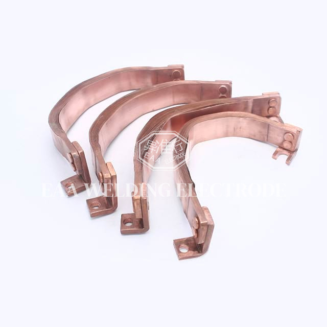
Engineers must match the specific connector type to the exact environmental application. You must carefully weigh core design characteristics, ideal field use cases, and inherent mechanical trade-offs.
Designers construct the copper foil flexible connector from highly stacked, ultra-thin copper sheets. Automated industrial machines press-weld these exact sheets tightly at the terminal contact areas. This precision process completely fuses the metal without needing any unreliable solder. It creates a solid, unified block at the ends while maintaining independent leaf flexibility in the middle.
These specialized connectors excel in high current density applications. They inherently offer a very low physical profile. You should confidently use them when facing strict spatial constraints inside compact battery racks. A Copper Foil Connector provides excellent absorption for standard 1D or 2D linear thermal expansion.
However, foil designs have highly specific mechanical trade-offs to monitor. They are noticeably less tolerant to violent, multi-directional twisting compared to woven braids. Forcing a stacked foil connector into a severe compound twist eventually causes internal layer delamination. Once the layers separate, electrical resistance climbs sharply.
The braided alternative features interwoven bare or heavily tinned copper wire strands. This intricate woven structure makes the final connection highly malleable and forgiving. A copper braided flexible cable easily bends in multiple complex directions simultaneously without tearing.
You should deploy braided designs for highly complex routing scenarios. They provide vital 3D flexibility in tight, unstructured spatial layouts. They heavily dominate in field environments experiencing severe, multi-axis vibration. Mobile ESS setups and highly modular C&I systems routinely rely on braided solutions to prevent vibration fatigue.
The primary engineering trade-off involves physical space utilization. A Copper Braided Cable typically requires more physical volume to achieve the exact same ampacity as foil. Furthermore, the woven micro-strands can fray dangerously if factory operators do not properly terminate them.
Table 1: Technical Comparison of Flexible Connections
Technical Feature | Foil Connector Architecture | Braided Cable Architecture |
|---|---|---|
Base Construction | Press-welded stacked ultra-thin sheets | Interwoven bare or tinned wire strands |
Flexibility Plane | 1D and 2D linear absorption | Complex 3D multi-axis bending |
Current Density | Exceptionally high in low structural profiles | Moderate, requires slightly more physical volume |
Vibration Tolerance | Good for standard HVAC/seismic shaking | Excellent for severe mobile environments |
Selecting the correct interconnection hardware demands rigorous technical evaluation. You cannot afford to compromise on raw base materials or international safety standards. System performance heavily relies on strict adherence to basic material science principles.
Long-term interconnection reliability always starts with the raw base metal. Specifications must strictly require T2 or C11000 grade copper for all internal pathways. This premium grade guarantees at least 99.9% molecular material purity. High purity directly ensures absolute minimal electrical resistance across the critical module links. Optimal electrical efficiency prevents wasted energy from turning into dangerous ambient heat. Lower purity base metals introduce microscopic impurities causing severe long-term thermal degradation.
Modern battery links operate in incredibly tight, high-voltage environments. Exposed bare metal poses unacceptable catastrophic short-circuit risks. You must evaluate various distinct insulation methods for high-voltage isolation. Industry-standard approaches include:
Liquid PVC dipping for seamless, contoured coverage.
Industrial heat-shrink tubing for rapid, cost-effective manufacturing.
Specialized elastomer spray coatings for extreme environments.
All utilized insulation materials must successfully meet strict UL 94 V-0 flame retardancy standards. An elastomer coating often provides far superior flexibility over standard stiff heat-shrink wraps.
Raw bare copper oxidizes incredibly quickly when exposed to standard environmental humidity. Aggressive oxidation dramatically increases electrical resistance at the vital contact pads. You must specify thick tin, heavy nickel, or pure silver plating on all terminal interfaces. Proper metal plating prevents destructive galvanic corrosion when connecting dissimilar metal terminals. It guarantees the delicate connection survives a highly demanding 10-to-20-year operational lifespan.
You must precisely calculate the required ampacity for extreme scenarios. Sizing the flexible link solely for normal nominal current invites absolute disaster. Storage systems routinely experience massive transient peak loads during sudden grid stabilization events. Intense short-circuit fault conditions generate massive, instantaneous electrical current spikes. The connection must easily survive these brutal thermal extremes without melting or mechanically failing. Accurate thermal fault ratings guarantee the system safely clears unexpected electrical faults.
Deploying new interconnection architecture carries distinct operational manufacturing risks. Engineering and procurement teams must aggressively vet their chosen supply chain before scaling up production volumes.
Inconsistent factory manufacturing processes introduce deeply hidden physical failure points. For layered foil connectors, the extreme danger lies in poor press-welding or weak diffusion bonding. Incomplete molecular bonding leads to severe layer delamination during daily thermal cycling. Delamination restricts heavy current flow and creates variable electrical resistance across different product batches. These dangerous inconsistencies cripple delicate system balancing efforts and immediately void critical safety certifications.
Partnering with a reliable copper foil connector supplier requires highly structured, careful scrutiny. Use the following detailed evaluation checklist during your initial vetting phase:
Rigorous Verification of Testing: Always demand raw empirical test data. Request comprehensive reports on temperature rise tests, 48-hour salt spray corrosion tests, and ultimate tensile strength thresholds.
Advanced Manufacturing Capabilities: Closely assess their factory shop floor technology. Look specifically for automated polymer diffusion welding equipment. Strictly avoid suppliers relying heavily on variable manual assembly techniques.
Customization & Rapid Scaling: Evaluate their internal engineering agility. Can they quickly prototype custom bend radii for new rack designs? Ensure they actively possess the financial capacity to scale production for massive megawatt-hour BESS deployments.
Never transition immediately to full-scale enterprise procurement. You should carefully initiate a highly targeted pilot program first. Conduct intensive small-batch testing under simulated peak thermal load conditions. Verify the provided empirical data perfectly matches real-world performance. Once the pilot program validates the mechanical and electrical integrity, confidently proceed to high-volume purchasing.
The initial design phase of any advanced energy storage system demands incredible precision. Choosing between layered foil and woven braided solutions remains a highly calculated engineering balance. You must carefully weigh spatial design limitations, peak electrical current capacity, and required multiaxial mechanical flexibility. Neither isolated solution fits every single storage use case perfectly.
Always remember the severe structural stakes involved in these architectural decisions. The upfront component cost of these interconnections remains incredibly low relative to the whole battery system. However, the ultimate cost of a localized electrical failure is undeniably catastrophic. Weak internal links easily cause thermal fires, destroy highly expensive battery modules, and permanently ruin corporate brand reputations.
Dedicated engineering and commercial procurement teams must take immediate, proactive steps today. Contact your shortlisted, highly certified manufacturing suppliers immediately. Request their detailed geometric technical drawings and independent thermal stress test reports. Rigorous upfront technical validation guarantees your massive battery systems operate safely and profitably for decades.
A: A high-quality flexible busbar generally lasts 15 to 20 years. This long lifespan aligns perfectly with the standard operational expectations of utility-scale storage systems. Proper tin or heavy nickel plating ensures a maintenance-free structural design by completely preventing surface oxidation. They easily withstand daily aggressive charge and discharge duty cycles and actively resist environmental degradation when properly insulated.
A: The Battery Management System strictly relies on precise voltage readings for active cell balancing. A poorly bonded connector introduces high contact resistance, immediately causing false voltage drops. The ultra-low contact resistance of a properly welded foil connector provides highly stable electrical pathways. This stability ensures the BMS logic receives highly accurate, real-time module-level data constantly.
A: Yes, they safely manage extreme high-voltage applications when properly insulated. Engineering teams use thick elastomer coatings or specialized heat-shrink tubing to electrically isolate the woven braids. System designers must also calculate exact physical clearance and creepage distances between adjacent cables. Strict adherence to UL and IEC insulation standards perfectly prevents dangerous arcing in high-voltage C&I systems.
A: Diffusion welding is a highly advanced molecular bonding process used to fuse thin copper sheets together. It applies extreme mechanical pressure and intense heat directly to the contact pads. This precise action bonds the copper atoms directly, completely eliminating the need for unreliable filler metals like solder. It perfectly maintains pure raw copper conductivity.


