


Views: 0 Author: Site Editor Publish Time: 2026-09-17 Origin: Site


Electric Vehicles (EV) and Energy Storage Systems (ESS) operate in incredibly high-stakes environments. They constantly face extreme current densities, continuous thermal cycling, and aggressive mechanical vibration. You simply cannot rely on traditional rigid busbars here. Rigid metals transfer kinetic stress directly to fragile battery module terminals. They also consume too much valuable space in tightly packed modern battery enclosures. We urgently need a better engineering approach.
This article objectively evaluates why flexible copper architectures now dominate as the industry standard. We will explore how engineers match specific product types to exact system requirements. You will learn to navigate the core differences between braided cables and foil designs. Furthermore, we will uncover crucial evaluation metrics for thermal management, insulation compliance, and lifecycle reliability.
Flexible copper connectors mitigate mechanical stress caused by thermal expansion and EV road vibration, protecting sensitive battery module terminals.
The choice between a Copper Foil Connector and a Copper Braided Cable depends on spatial constraints, required flexibility axes, and ampacity needs.
Evaluating a flexible copper power connector requires strict adherence to thermal management profiles, insulation compliance (UL94), and cycle-life testing.
Selecting a qualified flexible copper connector supplier hinges on their in-house testing capabilities, raw material purity, and custom tooling agility.
Modern battery platforms demand flawless electrical continuity. They must maintain this continuity while enduring severe physical punishment. Traditional rigid copper or aluminum busbars fundamentally fail to accommodate dynamic physical shifts. Engineers must frame this as a direct threat to system safety and longevity.
Electric vehicles experience continuous kinetic energy transfer from uneven road surfaces. Rigid connections act as rigid bridges. They transfer this kinetic energy directly to the battery cells. This relentless vibration leads to micro-cracks inside the cell structures. Terminal fatigue accelerates rapidly under these conditions. Over time, physical terminal connections weaken, creating high-resistance hotspots. These hotspots severely increase the risk of localized melting or thermal runaway.
High-voltage cycling generates intense localized heat. Components naturally expand when hot and contract when they cool down. Rigid busbars lack the mechanical tolerance to absorb this dimensional change. They forcefully push against battery modules during expansion. This places immense mechanical stress on the entire system geometry. A proper flexible solution absorbs this expansion internally without transferring force to adjacent components.
Modern high-density ESS racks require incredibly tight packaging. EV battery packs share this same demand for spatial efficiency. Engineers face complex routing scenarios within highly confined spaces. Rigid angles are nearly impossible to install efficiently in these tight corridors. We must route massive currents through winding paths. Rigid bars simply cannot navigate these complex geometries without demanding excessive clearance.
We measure success through strict lifecycle endurance. A connection solution must maintain zero electrical degradation across a 10-year or longer lifecycle. It must continually absorb mechanical shocks. It must perfectly accommodate thermal stress. It must achieve all this without compromising its original ampacity or insulation integrity.
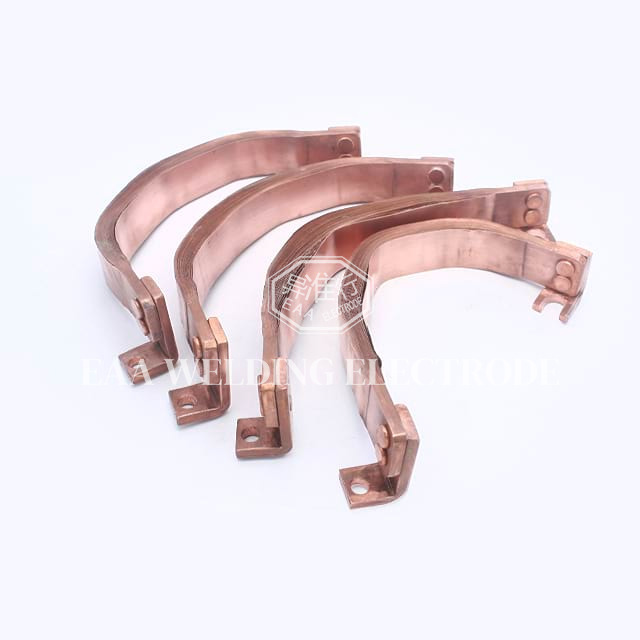
System designers generally choose between two primary flexible architectures. You must align the connector type directly with your specific mechanical environment. Misapplying these technologies leads to premature mechanical failure.
Manufacturers weave these cables from ultra-fine copper wires. Individual strand diameters often range from 0.05mm to 0.15mm. This complex woven structure allows for extreme multi-directional movement. It flexes seamlessly across the X, Y, and Z axes.
You should deploy braided configurations in environments facing severe, multi-axis vibration. They perfectly suit EV drive unit connections. They also excel at battery-to-chassis grounding applications. Moving parts demand this level of true omnidirectional freedom. Their primary advantage lies in unmatched flexibility and superior shock absorption capabilities.
Engineers construct these by stacking multiple layers of highly pure, thin copper foil. Manufacturers typically utilize press-welding or diffusion-welding techniques at the contact terminal areas. This fuses the ends into a solid block while leaving the center layers completely flexible.
These components shine in high-current, low-profile routing applications. You will find them inside dense battery modules and heavy-duty ESS racks. They work best where flexibility is primarily needed in one or two axes, such as simple bending. Their flat geometry delivers a distinct advantage. They offer higher current-carrying capacity in a much smaller cross-sectional area compared to braided cables. Furthermore, their flat surface provides highly predictable and efficient thermal dissipation.
Feature/Metric | Copper Braided Cable | Copper Foil Connector |
|---|---|---|
Flexibility Axes | Multi-axis (X, Y, Z) | Single or Dual-axis (primarily bending) |
Shock Absorption | Exceptional under heavy vibration | Moderate; best for thermal expansion |
Current Density | Standard | Very High (compact cross-section) |
Ideal Application | Drive units, chassis grounding | Internal battery modules, ESS racks |
Heat Dissipation | Good | Excellent (large flat surface area) |
Choosing the correct raw form factor is only the first step. You must rigorously evaluate these connectors against strict electrical and environmental standards. System safety relies entirely on these secondary engineering dimensions.
Current handling depends heavily on cross-sectional area and the AC skin effect. High-frequency inverters push current toward the outer surface of a conductor. Flat foil designs maximize this surface area, mitigating the skin effect efficiently. They handle massive continuous and peak currents with ease.
Heat dissipation rates differ significantly between the two designs. Evaluating surface area differences reveals that flat foil sheds heat faster than tightly bundled round braided designs. When thermal management profiles are exceptionally strict, flat geometries generally provide better convective cooling.
High-voltage environments demand aggressive insulation strategies. EV and ESS platforms routinely operate between 400V and 1000V. You must select appropriate sleeving materials. PVC, heat shrink tubing, and extruded silicone represent the most common choices.
UL94 Flame-Retardant Ratings: Your insulation must achieve a UL94 V-0 rating. It must self-extinguish immediately upon exposure to a direct flame.
Dielectric Strength: The material must resist electrical breakdown under extreme high-voltage spikes.
Environmental Resistance: Sleeving must withstand exposure to automotive fluids, battery coolants, and ambient humidity without degrading.
Bare copper oxidizes quickly in harsh environments. You must specify appropriate surface treatments for the terminal ends. Common plating options include tin, silver, or nickel.
Plating prevents destructive galvanic corrosion. This corrosion happens rapidly when copper connects directly to aluminum battery terminals. In high-humidity ESS environments, an unprotected connection will oxidize. Oxidation increases contact resistance, which subsequently generates dangerous localized heat. Tin plating serves as the standard industrial defense against this phenomenon.
Theory often clashes with assembly line realities. Engineering teams must anticipate manufacturing variations and installation hazards. Proper component selection smooths out these inevitable implementation bumps.
Manufacturing variations accumulate quickly in large systems. A deviation of just 0.5mm per battery module creates a massive alignment issue by the end of an ESS rack. Utilizing a well-designed copper foil flexible connector naturally absorbs these geometric variations. The foil flexes just enough to bridge the gap perfectly. This eliminates forced fits, prevents terminal stress, and prevents costly assembly line delays.
Scalable ESS configurations present unique installation challenges. Field technicians face severe safety hazards when manually bolting high-voltage connections in tight cabinets. We see a massive emerging need for connectors that support blind-mating or rapid installation. Fast-plugging terminals reduce labor time dramatically. They also remove the human error associated with improper torque wrench applications on traditional bolted joints.
You must watch out for specific failure modes during the design phase. Poor design parameters will destroy even the best materials.
Premature Fraying: You risk severe fraying in a copper braided flexible cable if you miscalculate the minimum bend radius. Forcing a tight bend stretches the outer wires beyond their tensile limit, snapping them individually.
Terminal Delamination: Poor-quality foil connectors often suffer from delamination. This occurs due to substandard diffusion welding at the terminal ends. If the layers separate, contact resistance spikes instantly.
Your supply chain dictates your overall system reliability. Procurement teams must look far beyond basic unit pricing. You must verify core engineering capabilities before approving a vendor for high-voltage applications.
Demand absolute transparency regarding raw materials. You must verify the supplier’s raw material sourcing protocols. Look for certifications guaranteeing the use of C11000 or T2 pure copper. The base material must guarantee an electrical conductivity rating exceeding 99.9% IACS (International Annealed Copper Standard). Inferior copper alloys contain impurities. These impurities drastically increase resistance and generate unwanted heat during operation.
A credible partner must provide extensive in-house testing data. Do not accept estimated performance figures. Ask them to produce documented evidence of the following:
Temperature Rise Tests: Verifying how hot the connector gets under maximum continuous load.
Tensile Strength Analysis: Proving the structural integrity of the welded terminal zones under mechanical pull forces.
Salt Spray Testing: Demonstrating long-term corrosion resistance, which is absolutely critical for coastal ESS deployments.
Off-the-shelf geometries rarely fit optimized battery packs. Evaluate the ability of the supplier to rapidly prototype complex geometries. They must quickly adapt their stamping and diffusion welding tooling. Furthermore, they need the agility to customize insulation profiles to match your specific EV chassis constraints or ESS rack designs. Speed in the prototyping phase defines your time-to-market success.
The transition toward flexible copper architectures represents a mandatory risk-mitigation strategy for modern battery systems. It is absolutely not a mere design preference. High current loads, thermal shifting, and violent road vibrations will destroy rigid connections over time.
Your specific application environment dictates your material choices. Choosing the right form factor—whether multi-axis braid or high-ampacity foil—strictly dictates your long-term system reliability. A mismatch here guarantees premature fatigue.
Engineers and procurement managers must take immediate action on their current build cycles. You should explicitly request material purity certifications and thermal rise test data when evaluating your next project requirements. Demand rigorous testing evidence from your manufacturing partners to ensure absolute safety and performance.
A: Foil generally offers higher ampacity for a given physical profile. Its flat, dense construction provides better internal heat dissipation and larger surface area per cross-section. While braided cables handle high currents well, foil achieves greater density in tighter spaces. Exact capacity figures always depend on the final cross-sectional area of the chosen design.
A: Yes, they are highly suitable. However, you must ensure the insulation sleeving meets strict requirements. The chosen dielectric materials must exceed the specific breakdown voltage ratings required by 800V+ isolation standards. Proper UL94-rated extruded silicone or specialized heat shrink ensures complete high-voltage safety.
A: Plating primarily prevents oxidation and dangerous galvanic corrosion. Manufacturers apply tin, nickel, or silver to the terminal pads. This surface treatment lowers contact resistance permanently. It ensures long-term electrical stability when the copper interacts with dissimilar metals, like aluminum battery posts, in harsh environments.
A: They are excellent for single-axis flex, such as simple bending, and they easily absorb thermal expansion. However, extreme multi-axis vibration—like the complex kinetic forces found near EV drive units—is usually better served by a woven braided cable. Braids offer true unrestricted 3D movement without fatiguing.


