


Views: 0 Author: Site Editor Publish Time: 2026-06-10 Origin: Site


High-volume sheet metal joining relies entirely on cycle speed and process consistency. In these demanding industrial environments, the Spot Welding Electrode often acts as the critical bottleneck dictating final production quality. You simply cannot afford to treat these engineered components as standard, disposable consumables. Choosing the wrong electrode material or an incorrect tip geometry directly leads to weak structural welds. You will likely experience excessive metal splatter, rapid tooling wear, and heavily compromised joint integrity.
This misstep inevitably forces increased downtime for constant tip dressing and maintenance. When automated production lines stop for tooling corrections, factory profitability drops rapidly. We designed this article to serve as a comprehensive technical and procurement guide. You will learn how to evaluate different copper alloys and match them to stubborn sheet metals. By understanding the core thermal dynamics, you can confidently scale your manufacturing processes and keep production running smoothly without unexpected interruptions.
The rule of inverse conductivity: Weld highly resistive metals (like steel) with highly conductive electrodes (copper alloys); weld highly conductive metals (like aluminum) with resistive electrodes (tungsten/molybdenum).
Ideal sheet metal thickness for standard spot welding is 0.5mm to 3mm; pushing beyond this requires specialized high-current circuitry and custom electrode designs.
Galvanized steel requires specific RWMA Class 2 (Chromium-Zirconium-Copper) electrodes to prevent zinc adhesion and tip degradation.
Destructive testing (the "Peel Test") remains the industry standard for verifying the metallurgical bond of the weld nugget.
To master resistance welding, you must first understand the thermodynamic formula governing the process: Q=I²Rt. This equation maps exactly how energy enters your substrate. Here, Q represents the total heat energy generated. I is the welding current. R stands for the electrical resistance across the metal interface. Finally, t equals the precise duration the current flows. The electrode performs two simultaneous, critical jobs. It safely conducts the massive electrical current while actively applying physical pressure to manage the contact resistance.
Achieving a zero-defect joint requires strict adherence to a three-stage mechanical cycle. Skipping or rushing any of these phases practically guarantees a failed weld. The standard cycle includes:
Squeeze Time: The equipment applies physical pressure through the copper tips before any current flows. This forces the two metal sheets together, ensuring optimal surface contact and stabilizing initial electrical resistance.
Weld Time: A millisecond burst of electrical current travels through the metal. You typically see 1,000 to 10,000 amps delivered at extremely low voltages. The high resistance between the two sheets transforms this electrical energy into intense heat, melting the target area into a molten nugget.
Hold Time: The electrical current stops completely, but the physical clamping pressure remains engaged. This critical step forges the two sheets together. The pressure holds the liquid metal secure as it rapidly cools and solidifies into a permanent metallurgical bond.
When you size your tooling correctly, you successfully minimize the Heat-Affected Zone (HAZ). A small, controlled HAZ prevents unwanted warping in thin-gauge metals. Proper thermal management allows the base materials to retain their original structural integrity. They fuse perfectly without requiring any external filler materials or shielding gases.
Engineers evaluate and group these tools using the Resistance Welder Manufacturers' Association (RWMA) classifications. This standardized framework ensures you select the correct metallurgical properties for your specific application. You generally choose between three primary copper-based classes for standard industrial welding.
Each class balances electrical conductivity against physical hardness. You must match the alloy to the thermal properties of your workpiece.
Class 1 (Zirconium-Copper): This alloy delivers the highest electrical conductivity while maintaining strong resistance to thermal deformation. You should use Class 1 exclusively when joining aluminum and magnesium alloys, which naturally demand rapid heat transfer.
Class 2 (Chromium-Copper / Chrome-Zirconium-Copper): We consider this the absolute workhorse of the automotive and manufacturing industries. It offers the best possible balance of physical hardness and electrical conductivity. It performs exceptionally well on cold-rolled steel, high-strength steel, and stainless steel sheet metal.
Class 3 (Beryllium-Copper): This material provides maximum physical hardness but suffers from significantly lower electrical conductivity. You will typically deploy Class 3 alloys for high-resistance welding conditions, such as joining thick, heavy-gauge metals or applying projection welding techniques.
You face a unique physical challenge when joining highly conductive components like copper busbars or gold-plated electronic switchgear. If you try to use standard copper tooling, the electrical current simply passes through the workpiece without generating enough friction or heat. To fix this, you must rely on refractory metals like Molybdenum and Tungsten. Because these metals possess very high electrical resistance, they intentionally generate intense heat right at the tip. They essentially act as highly resistive heating elements, melting the conductive substrates beneath them to form a solid bond.
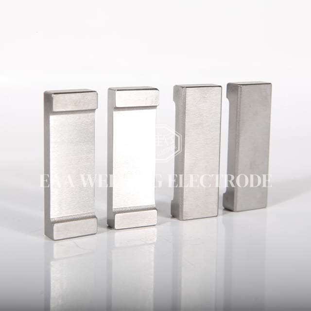
Standard low-carbon steel rarely presents problems. However, modern manufacturing often demands corrosion-resistant coatings and lightweight alloys. These advanced materials introduce complex metallurgical hurdles on the factory floor.
Automakers use galvanized steel extensively to prevent rust. The primary problem lies in the zinc coating. Zinc melts at a much lower temperature than the underlying steel. During the weld cycle, this liquefied zinc instantly alloys with standard copper tips. We call this phenomenon "brassing." It causes severe sticking, massive surface degradation, and rapid pitting.
To combat zinc poisoning, you must specify Cr-Zr-Cu (Chromium-Zirconium-Copper) alloys. The addition of zirconium actively resists zinc adhesion, preserving the face geometry for far longer production runs. Furthermore, you must prioritize compliance and safety. Vaporized zinc creates toxic fumes. Factories must install robust fume extraction systems to prevent operators from developing Metal Fume Fever, a severe respiratory condition caused by inhaling these volatile metallic byproducts.
Welding aluminum often frustrates novice engineers. The metal possesses incredibly high thermal and electrical conductivity. Worse still, it naturally forms a stubborn, highly resistive oxide layer on its surface. This combination makes forming a stable, consistent nugget incredibly difficult. It pulls heat away from the joint almost as quickly as you can apply it.
Overcoming this requires specialized power supplies. Standard alternating current (AC) welders struggle here. You need Capacitor Discharge (CD) systems or Mid-Frequency Direct Current (MFDC) inverters. These machines deliver a massive, instantaneous energy spike capable of punching right through the oxide layer. You also need strict maintenance protocols. Aluminum contaminates copper tips quickly, so frequent tip dressing remains mandatory.
Even if you select the perfect alloy, incorrect machine settings will ruin your assembly. Two mechanical variables dictate your success: the physical diameter of the face and the clamping pressure applied by the pneumatic cylinders.
The size of the contact patch controls the current density. Modifying this diameter changes the entire thermal profile of the joint.
Too Small: A narrow face concentrates the current too intensely. While it melts the metal quickly, it creates a weak, undersized nugget. This tiny joint often fails under basic shear stress testing. It also drives the tip deep into the sheet, leaving unacceptable surface damage.
Too Large: An oversized face disperses the current density over too broad an area. The interface never reaches the required melting temperature. This leads to incomplete fusion, weak surface tacking, and hidden structural voids inside the joint.
Managing resistance requires precise physical clamping. The metal sheets must touch intimately before the current fires.
Insufficient Pressure: If the sheets remain slightly separated, the electrical current jumps the gap. This causes intense surface arcing and violent molten metal expulsion, known as splatter. It degrades the copper tips prematurely and leaves dangerous burrs on the workpiece.
Excessive Pressure: Squeezing the sheets too hard creates a different problem. It reduces the interface resistance too much. Without enough resistance, the current fails to generate the required heat for proper melting. Additionally, excessive force creates deep surface indentations, permanently weakening the parent metal.
Advanced manufacturers no longer rely purely on visual inspections. They integrate inline analytical tools to monitor process health in real time. Modern production lines utilize laser vibrometry to measure microscopic vibrations in the tooling during the squeeze phase. By analyzing these acoustic signatures, automated systems can detect potential splatter events up to 70 milliseconds before they actually occur. The controller instantly adjusts the current to save the weld, ensuring near-perfect quality control.
The automotive sector continually pushes the boundaries of resistance joining. The rise of Electric Vehicles (EVs) demands lighter, stiffer chassis designs to offset heavy battery packs. This requirement ushered in the era of weld-bonding.
Modern vehicle architectures frequently require joining complex three-sheet stack-ups. To achieve maximum rigidity and crash safety, engineers now apply heavy industrial structural adhesives between the metal layers before clamping them together. A specialized Spot Welding Electrode must fire directly through these wet glue layers to fuse the steel plates underneath.
Adhesives act as electrical insulators. If you fire the main current while glue sits between the sheets, the weld will fail entirely. You must alter your standard parameters to compensate. Programmers typically extend the initial squeeze time significantly. This extra mechanical duration literally squishes the wet adhesive out of the immediate contact zone. Alternatively, the machine can pulse a low-amperage pre-heating current. This softens the surrounding adhesive, allowing the copper tips to establish direct steel-to-steel contact before the massive primary welding current fires.
Why do aerospace and automotive giants like Tesla and Boeing rely so heavily on advanced resistance joining? The Return on Investment (ROI) is staggering. The process achieves permanent metallurgical bonds in mere milliseconds. Unlike MIG or TIG welding, it requires zero consumable filler wires or expensive shielding gases. Once you optimize the equipment, the cost-per-weld drops to fractions of a cent, making it the ultimate solution for high-volume, automated robotic manufacturing.
Securing high-quality joints consistently requires partnering with a reliable supplier. You cannot simply buy the cheapest copper tips available online. The microscopic metallurgical structure of your tooling matters immensely.
You must assess your vendor's capacity to deliver consistently alloyed, void-free copper materials. Internal casting voids or inconsistent chromium distribution will create localized hot spots on the tip face. This causes erratic melting and unexpected downtime on fast-paced automated lines. A dependable Spot Welding Electrode manufacturer utilizes strict metallurgical casting techniques to ensure uniform density across every batch.
Standard pointed tips do not work for every assembly. A qualified supplier should offer extensive custom-machined profiles. Depending on your joint accessibility and sheet metal configuration, you might need offset geometries, flat faces, or specialized dome radiuses. Working with a supplier capable of rapid custom machining allows you to reach difficult corners inside complex assemblies without compromising clamp pressure.
Always demand full material certifications. Uncertified, low-grade copper alloys degrade at unpredictable rates. As the face flattens and mushrooms prematurely, it violently skews the Q=I²Rt balance. This leads directly to latent, hidden weld failures in the field. Reputable suppliers guarantee their RWMA classifications, giving your engineering team the confidence to lock in their automated parameters.
Parameter Issue | Visual Indicator | Structural Consequence |
|---|---|---|
Insufficient Squeeze Time | Heavy metal splatter and surface arcing. | Porous nugget, rapid tip degradation. |
Excessive Clamping Pressure | Deep indentations on the sheet surface. | Cold weld due to low contact resistance. |
Electrode Face Too Large | Wide, flat, discolored contact zone. | Incomplete fusion, weak shear strength. |
Incorrect Alloy (Galvanized) | Heavy zinc buildup and black pitting on tip. | Erratic heat generation, frequent sticking. |
The spot welding electrode is far from a passive, throwaway consumable. It operates as the highly active, critical controller of both thermal dynamics and mechanical force. By balancing electrical current, precise timing, and physical pressure, these copper tools transform simple sheet metal into rigid structural assemblies. The physics remain unforgiving; even minor deviations in your tooling geometry or alloy composition will disrupt the delicate energy transfer required for a solid joint.
We recommend taking immediate action on your factory floor. Engineering and procurement teams should collaboratively audit their current tooling lifespan. Review your daily tip dressing frequencies. If your operators constantly stop to clean or replace copper, you are losing money. Run destructive peel tests this week to verify your baseline strength. Use this data to determine if upgrading your RWMA class or partnering with a specialized, certified manufacturer will successfully lower your long-term cost-per-weld.
A: The industry standard is the destructive "Peel Test." When pulling two welded sheets apart, a successful weld will tear a clean "button" or "nugget" out of the parent metal rather than breaking cleanly at the interface.
A: While 0.5mm to 3mm is the optimal range, welding >3mm steel is possible but requires heavy-duty industrial equipment with specialized high-amperage circuitry and substantially higher clamping force.
A: Visual indicators include irregular or non-circular weld nuggets, excessive surface indentations, increased metal expulsion (sparks/splatter), and physical "mushrooming" (flattening) of the electrode tip.
A: This typically occurs when welding galvanized steel with an incorrect electrode alloy, or when clamping pressure is too low, causing surface arcing that microscopically welds the tip to the workpiece.


